
Summary: PM Best Practices and Core Program Structure for Hybrid integrated programs using Phased HW – Agile SW, mixed-technologies. Full-Program agility via automated plan tools with continuous plan update.
This Series, “Advice for Program Managers”: Modern Program Management requires skills and methods specialized to characteristics of its industry; to technologies of its produced products and services; and to management of its organization. In execution, Program Management envisions, creates, organizes, and rationalizes information and leadership across all these domains. The leadership and information created make Program Management an integral part of management of a majority of work flowing through an organization.
BACK to Series Start — Advice for Program Managers: 1-Program Management Opportunity
The Series also solicits contributions to this Blog site, to extend coverage of PM Best Practices and Core Program Structure to a broadening set of Specializations.
Published concurrently on www.softtoyssoftware.com.
PM Specialization Due to Technology and Handling
Core Technology and Special Handling are factors that drive need for specialized methodologies and skills in Program Management. Examples: There are large management differences among developing ASIC semiconductors; vs. System-Level or Board-Level hardware development and privileged code; or non-privileged code in virtualized environments. Differences exist also among construction types: residential; subdivision development; multi-story commercial; industrial buildings and more. Underlying technologies among all these and others imply specific and predictable difference of scheduled tasks, logistics, function-schedule dependencies, physical processing, and partners.
Specialization occurs in familiarity with the primary subject matter, as well as with tool environments for design and execution; libraries, APIs, interfaces, and standards; and in familiarity with current common art from both published, and proprietary sources from prior experience.
Knowledge of specifics in planning and execution based on program type is essential to effective Program Management, going far beyond the typical Program Management basic training.
PM Best Practices and Core Program Structure. It would be impossible to create full training programs for the programs of these varying technologies. Not only is the subject matter huge and diverse, but also proprietary information will not be readily shared.
An approach can be taken though, that captures “PM Best Practices and Core Program Structure” for Program Management tasks and skills for varying program technologies into an available archive. Without being comprehensive, this nevertheless promises to be current as practitioners contribute to such an archive. If archive articles could be “scored” by qualified practitioners, they could efficiently enhance skills of Program Managers.
Specialization Pages Solicited for PM Contributions
Examples in these Blog series initial posts are based on my experience in system platform projects, described in linked posts.
There are many opportunities for further Authorship and Contribution to be published within this framework
- Software above abstraction level: full-stack, web, database, commercial, financial, business, tools
- Software below abstraction level: firmware/Test, Driver/kernel/boot, access/transport, Management
- “Pure Agile” environments
- “Full-Stack” projects
- Artificial Intelligence
- IT Infrastructure, Dev Tools, Service deployment…
- Construction: Residential, Commercial, Hi-Rise, Industrial et al.
- Pharma
- Medical Equipment
- Transportation Equipment
- Semiconductor Processes
PM Structure and Best Practices for System Programs
SDLC To hear all the rhetoric about Agile, you’d think that there are two choices: Waterfall (which is ponderous, inflexible, old-school, and horrible), or Agile (which reflects humanism and is wonderful). Unfortunately, Agile methodologies don’t well-support technologies that involve materials, partners, organizations, specialties, dependencies, durations and quantification. The real world, and real products, may require some of those. But the choice given is a “false choice” logical fallacy, and fortunately those are not the only two possibilities! So use or adapt Agile methodologies where appropriate to Program technology and organizational constraints. Otherwise, use or adapt other methodologies supporting those constraints, maintaining an Agile Mindset embodied by adaptability and timeliness.
Actually, there are “standard” methodologies derived from SDLC (“Software Development Life Cycle”) that are more flexible than basic Waterfall and include others with varying degrees of wonderfulness up to and including Agile. In this article, methodology will be described that supports co-existence of Agile with hardware methodologies for System development in a common Program. Then 6-Quantified Agile for Hardware, describes extension of Agile methodologies deeper into hardware development while concurrently honoring the quantifications needed for hardware development.
SDLC (ISO/IEC 12207; “Software Development Lifecycle” – please read this Tutorial!) starts by defining the basic SDLC stages (Planning, Defining, Designing, Building, Testing, Deployment). Then the methodology further defines SDLC Models followed in industry (Waterfall, Iterative, Spiral, V, Big Bang, Agile, RAD and Prototype). These vary in greater to lesser degrees of management, simplicity, flexibility, parallelism, incremental-ism, sequentiality, risk, coordination, product complexity and the like. These can be adapted to best-support organizational reality and technology of the product to be developed. For a particular example, in each of the SDLC Models some or all of the work “branches” that include “design-code-integrate-test” steps, might be replaced with Sprint cycles.
The methodology described throughout this series of articles supports SDLC stages, and further invokes elements of Iterative and Spiral SDLC methodologies with quantification to support multiple development methodologies for multiple technologies, as is common in systems. The resulting structure particularly supports system development involving multiple software modules (Agile, real-time decisions) and hardware modules (parallel, iterative, planned and real-time, quantified) to be developed, integrated, and productized as a system.
Phased Methodology vs. Waterfall, Phase-Gate, and Agile Methodologies: System development programs include hardware and software development for a key system element (server, router, storage et al.) together with physical systems to test and use it. This article describes core structure and practices for program management of system development programs.
Hardware development involves several distinct technologies, many inter-dependencies, several partners, and particular construction sequences requiring time duration and cost. These require need for bringup of production capability for the particular product developed, and particular validation steps covering both the product design and the production process. Each of these imposes quantitative requirements, including time, logistics, and finance on all aspects of the development Program – hardware, software, production, and support efforts.
Phased Methodology is not Waterfall, nor is it Stage-Gate. Those are described as sequential processes of requirements-design-development-qual-production, whereas the Phased Methodology described here involves repeated cycles iterating incremental design and qual, running several tracks in parallel through the cycles. Iterated cycles directly address progress along Tracks that include design of hardware and software product function and physical implementation, production capability of the product, required finance, qualification of each product increment, and ultimately deploying product support logistics.
Phased Methodology does not preclude use of Agile development methodologies where that is convenient. In fact, in System programs several methodologies are in use simultaneously, embedded within the overall Program. Methodologies may be unique for hardware development, software development, for materials handling, for qual processes, and for partner fabrication. The Phased Methodology discussed in this post to manage the overall Program conveniently handles multiple embedded methodologies, synchronizing them at a limited number of points, as will be described in the post.
Parallel operation is achieved among the Tracks, bringing up hardware, software, qual and production concurrently, as well as by parallel operation among the iterated cycles themselves. The iterated cycles are synchronized periodically, Track-by-Track, to maintain design integrity among them for qual (“Qualification Test”). Managing and sequencing of one iteration cycle dependent upon completion of work in prior cycles minimizes material risk and assures product integrity while still allowing significant parallel work. Parallel work decreases elapsed development time, speeding time-to-market and therefore revenue.
The result is that Phased Methodology uses parallel work at several levels throughout the Program to minimize or even eliminate time wasted due to poorly sequenced dependencies or due to material lead-time, managing dependencies to ensure design integrity.
Quantification is about details at whatever level is needed to track, manage, and report. To do that effectively, you need to foresee, represent tangibly, and integrate the combinations of elements, processes and time that define the Program. Then quantify those combinations and report them in ways useful to consumers of your work – buyers, builders, testers, controllers. You need to understand the product, the organizational processes, and your consumers. This is “Inside Baseball” for sure.
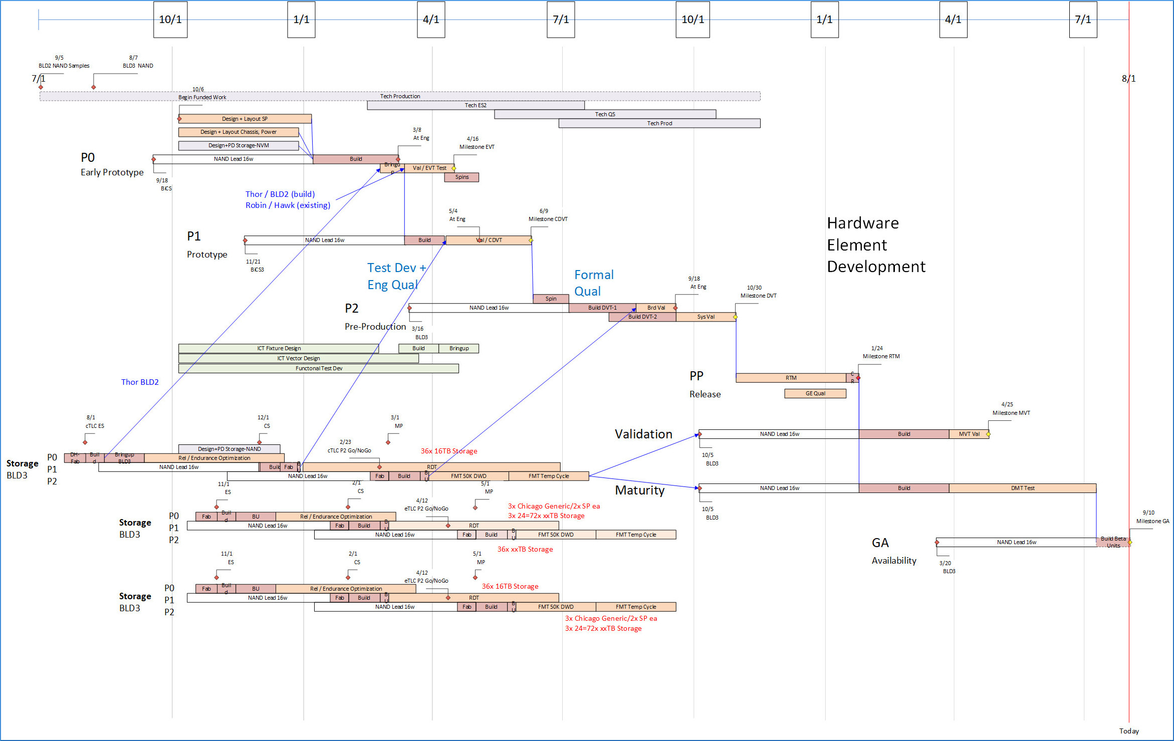
Complex programs require quantification of time, logistics, and finances. To quantify these programs, “Integration Cycles” are created and provisioned in the program GANTT/schedule, shown as the multicolor parallel bands in images below in this post. Each Integration Cycle handles a sequence of design update, material acquisition, fab, build, synchronization with other Program elements, assembly, test, integration, and qual test.
So, this Post is about specialization for PMs who need to quantify their programs. This Post describes quantification for a program using Phased methodology to develop hardware and software for system products. A later Post will discuss how such quantification can be overlain onto a program managed using Agile methodology. That’s also Inside Baseball.
Design the Program Structure.
Build a plan. Start simple and add layers. Plan early, and continuously extend and update the plan. This is far more efficient than leveraging the organization to fix something that could have been avoided by a better plan. Continuous updates to the plan force the plan to converge with reality quickly, at minimum describing “The best-known path from here”. You get good at this, and the organization develops expertise at it.
Predict: the future (envision and represent development, qualification, release, and continued enhancement of your program), Quantify that future, then Make that future Happen.
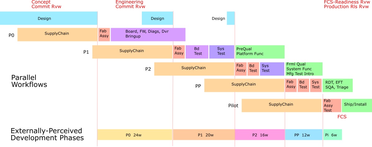
Envision and sketch out a skeleton sequencing the program at all major levels. Not in detail yet, just the flow. Start with one facet and layer the next onto it updating the base as needed. Element-by-Element, Module-by-Module. Then Assembly-level-by-assembly-level, then Integration-Cycle-by-Integration-Cycle of elements and assemblies. To each Integration Cycle, add Qual Test-by-Qual Test, by element and assembly. Throughout this structure, identify Function-schedule dependencies (i.e., dependence on function availability at a particular schedule point). Identify function synchronization points and split the structure to Integration Cycles/Phases (Table figure below). Focus on Integration Cycles as Phases: sequences of design update, material acquisition, fab, build, synchronization with other Program elements, assembly, test, integration, and qual test. As Qual tests complete, sketch endgame customer acceptance test, fulfilment pack-and-ship. Scale durations into tasks. If terms used in this Post don’t represent tasks for your Program that’s fine, envision the sequence that does. This skeleton is what you will quantify. Real life is going to roll out somehow, your job here is to foresee what it will be, then quantify it and make that happen.
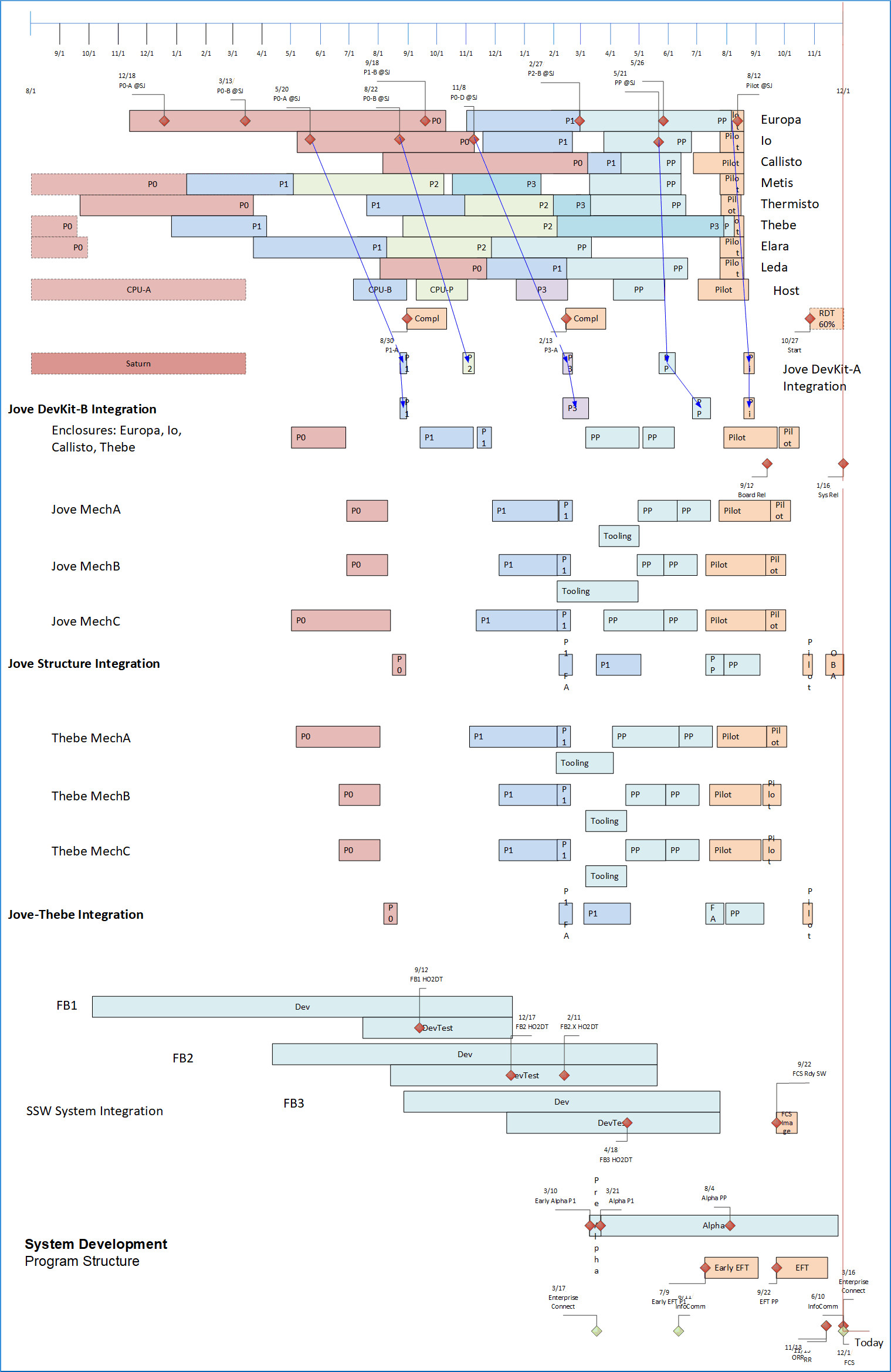
Schedule Structure Each Program element (hardware or software managed entity – board, metal, enclosure, module, capability) is represented by tasks for design, Prototype Cycle (materials, fab, build, assembly, manufacturing test) and Qual test repeated through each Integration Cycle/Phase. Program elements are then aggregated into assemblies in each Integration Cycle, driving assembly and test tasks. Manufacturing Test is included for element and assembly builds. System integration of assemblies available from internal or external sources, with schedule represented by assembly and test. Qual test activities including bringup, corner test, PVT, pre-Qual and formal Qual (environmental, ESD) and compliance (safety, emissions, privacy/financial; by country) are represented as Qual within appropriate phases and drive to end-game. Testing further includes Software Unit Test, release to SQA, Integration Test, and Compliances.
Product Requirements from the Product Management Business Plan constrain the FCS schedule of the Integration Cycles. Integration dates within the Integration Cycles constrain Element development plans.
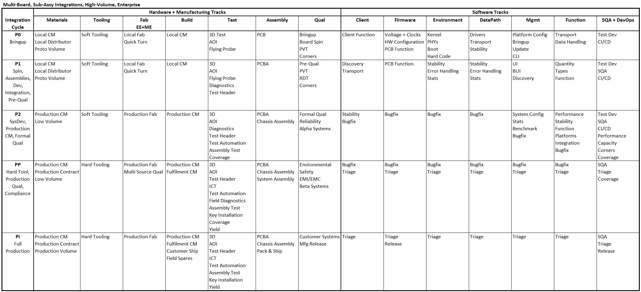
Tracks: System Programs consist of parallel development among multiple elements participating multiple Integration Cycles. Multiple Tracks describe progress across the Integration Cycles. Examples of Track sequences:
- Materials: Off-the-shelf > local CM proto purchase > Remote CM proto purchase > Low-volume production > production volume procurement
- Hardware: Design, first Fab, Bringup, pre-Qual > formal Qual > Compliance > product introduction.
- Element Fab: Local Quick-Turn Proto > Production Fab House > Multiple Source Fab Qual.
- Manufacturing: Prototype element construction > assembly construction > Assembly test, system construction > pilot production.
- Hardware Test: Element optical, flying probe > element diagnostics, test header > Multi-Element Assembly, Automated config and Test > Security Key installation
- Software: Platform design and bringup > Port in prior-gen functionality > develop capability of new platform function > develop aspirational functionality > post-release feature additions. (Table shown below illustrates multiple software tracks: Client, Environment, Data Path, etc.).
- Qual Test: HW/FW manual bringup, PVT, margin, corner test, pre-qual test > formal Qual > compliance and certification > countries. (Qual covers product hardware, software, user experience, margins and exception behavior, multi-source suppliers, materials, build, assembly and test processes, capabilities in worldwide physical and legal environments.)
For an Enterprise project involving hardware with multiple board assemblies and high-volume production, Tracks might be defined as:
For a single-board product, low-volume with high-volume production deferred to a later period, with limited integrations, and deferred volume Qual tasks, Track definitions might be simplified somewhat:
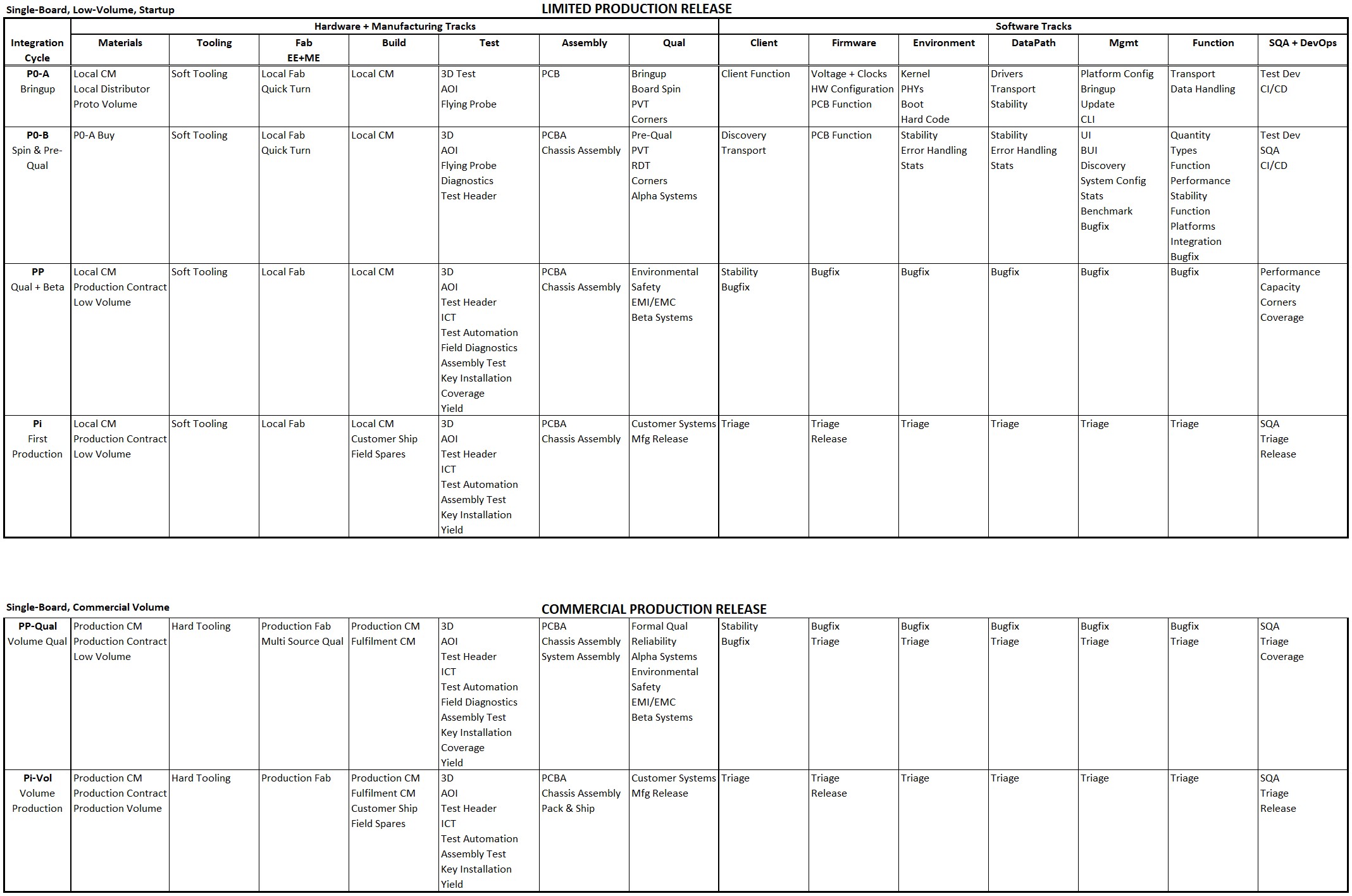
Function is listed for each Integration Cycle (horizontally), for each Track (vertically) to be incorporated into builds and testing of that Integration Cycle. Functionality for any Track in that Integration Cycle may have dependency on function listed for any other Track. Function listed is minimum planned function; greater function than listed could be delivered; less function delivered requires a workaround. Greater function than listed can be designed, integrated, and distributed throughout the Integration Cycle. The Program Manager usually creates a strawman, to be iterated to achieve agreement among stakeholders.
These images also foreshadow how we can organize Agile methodology sprints to develop product function and organizational capabilities along tracks, integration cycle by integration cycle, to manage the Program. That will be discussed in Post Advice for Program Managers: 6-Quantified Agile for Hardware.
Implementation Examples: The descriptions above are schematic, to illustrate concepts of parallel sequenced phases including integration sequences, with tracks across the phases advancing and sequencing development among multiple development and operational domains. A table describing intent of each phase, including criteria to initiate non-repudiable tasks in subsequent phases, is also illustrated.
In practice, to implement these concepts, detailed work is identified and quantified with durations and dependencies. This is incorporated into software tools for purposes of tangible planning and reporting coordinating domains, for execution of logistics operations, and for advising sequencing and initiation of specific work items as shown in the following figures. This supports, even drives, development of the whole program plan optimized among all domains.
Remember that these plans are not fixed, instead they are continually updated to reflect changes, current reality, and outlook and to mitigate adversities. This in turn supports agile mindset, again in all domains. Use of automated tools simplifies that work and helps assure plan integrity across included domains.
First, illustration of planned work for items of a functional element participating in a system development program. Development Phases are shown by the work sequences advancing diagonally down and across the figure. An external technology dependency is shown across the top, and a sub-project investigation and developing a sub-component of the element is shown at bottom left.
In practice, each functional element of a system development program would have such a defined plan. Prototype copies of the element built in each Phase shown, are used in integration steps for that phase at assembly-level and system-level, shown in a subsequent figure.
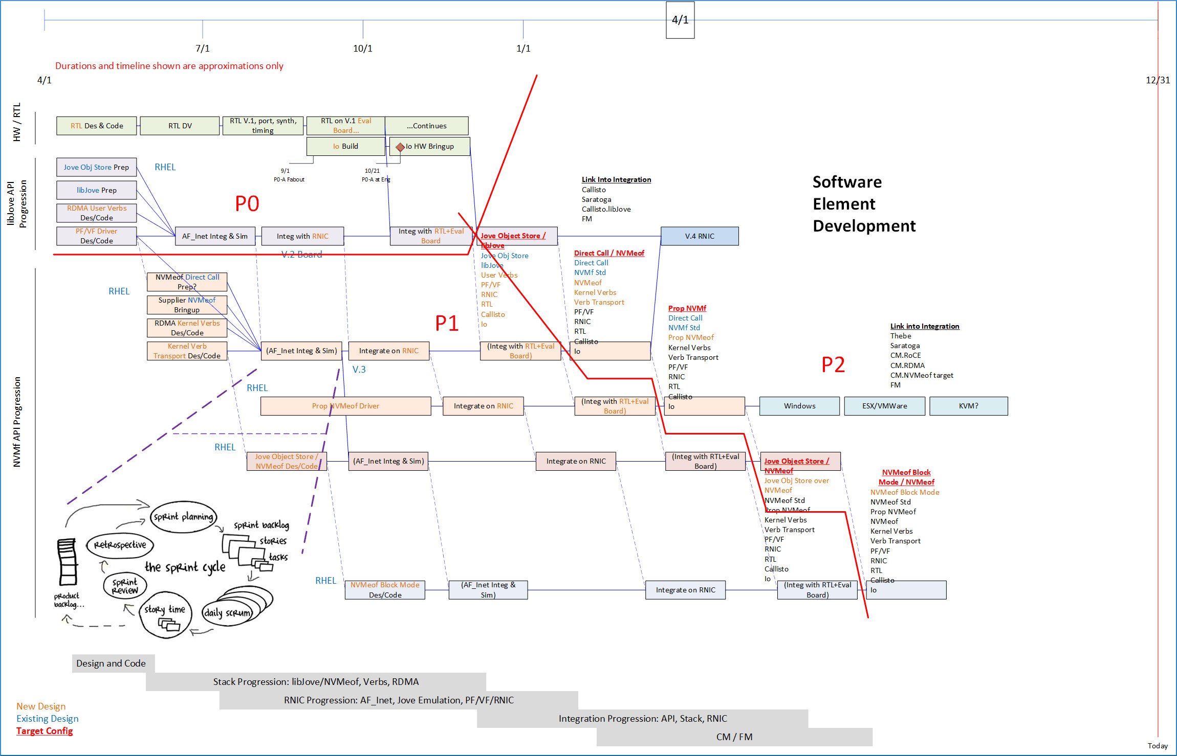
Second, illustration of planned work in parallel for software across multiple phases, showing integration among software functional modules with dependencies among software and hardware components.
Again, multiple software elements in a system program are likely to each have such a plan for unit development, and integration among other elements of the system program.
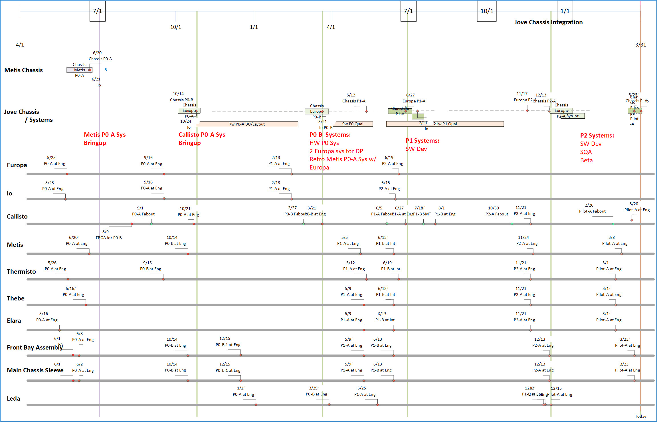
Then, for integration steps, illustration of a plan for each phase, for all element assemblies, and for systems comprised of multiple hardware and software elements. A specific system-wide plan for integration should exist catching dependencies for build and integration, from elements and sub-elements, logistics, to support integration steps defined in the plan. This plan is extremely cross-functional, and therefore is most likely driven by the Program Manager.
To catch dependencies, milestones for integration from each element and for each phase are extracted from hardware and software element plans. The image shows development coordination among all system elements timed to support integration steps. Notice that timing coordination tightens as dependencies are resolved as development progresses.
Assembly- and system-integration steps produce tangible hardware and software deliverables to be used in testing, for broader development, and for operational use, intended for the phase.
Focus on Critical Path: Identify, design, and maintain the planned critical path. Mitigate impacts to critical path, and thereby to overall Schedule.
It’s important to understand what critical path entails: By definition Critical path is the series of tasks leading to project endpoint(s) that has zero slack time in any task in that path. Endpoints typically include First Customer Ship (FCS). GANTT tools such as MS Project will identify Critical Path automatically. Once identified, you must clean it up and manage it.
Capabilities of elements in each of these Integration Cycle/Phase sequences are synchronized and planned in advance with focus on Integration Cycles each gauging progression of the effort. Usually, one element stands out as pacing the schedule due to its availability in the sequences of design, construction, and test. Integration points then synchronize all other elements with that long-pole element, and this determines the critical path for the Program as a whole.
The Program Manager should design the Program critical path, overlapping as much progress as possible in parallel with non-compressible tasks (often external such as fab, build, some Qual tasks, most Certification tasks); and to execute in parallel even those non-compressible tasks among each other as well. The critical path will then run through a set of non-compressible tasks, minimized because as much work as possible is overlapped with the non-compressible tasks.
Most tasks in a Program are not on critical path and will have some slack, which gives people some latitude. People on the critical path will be loaded, however. It often happens that the same people remain on critical path over and over. Typically, these are the core contributors in the organization. Managing critical path includes balancing work for these individuals. Prioritize and sequence critical path work as possible, find alternatives, work with line management to spread such work among multiple individuals. The organization and your Program need to retain these people.
The methodology for this is discussed in Complex Program Management and other posts linked below in this post. An optional set of free tools that exemplifies solutions or can be used directly, is provided on my website: http://www.softtoyssoftware.com/dbnet/programmingprojects/powerquerytool.htm.
Quantify the Program Structure.
Build a plan to implement this flow. “A dream without a plan is just a wish” – Antoine de Saint-Exupéry. It’s Program Management who build detailed plans for organizational work, materials, finances, and time, in order to realize the product or service at the center of the business plan. Now you put detail on the flow you sketched. You’ve built the foundation and added some rooms, now decorate them. Focus on key elements and develop schedule, typically a GANTT especially targeting integration points and requirements, then allocation, product structure program BOM, builds, dates, and element data.
Specifics of implementation of these Tables, GANTT, and visualizations are fully implemented in a Program reference design on my website, and they are illustrated in images below in the section in this Post on Program Logistics. They are free. You could look at the structures of the Tables and GANTT, the design of the Excel and visualizations to inform your own design. Or you could use the reference design as the basis for your Program quantification – the design is scalable from small to large, and I’ve used it for several large projects. The tools use PowerQuery in Excel or can use MS Access or SQL Server. These tools are available at my website www.softtoyssoftware.com with further description on that website. You can post questions below on this Post.
Estimating Durations: In a system program with both hardware and software development elements, critical path tends to run through hardware development up through first prototype build, and after that runs through software development. Hardware design, including technology, logic, electrical and mechanical, and supplier choices, is mostly completed prior to initial fabout, the first step in building board elements.
After initial hardware prototype build, hardware schedule is dominated by Integration Cycles including Prototype Cycles. The multiple Integration Cycles partially overlap long-duration material acquisition and qual test cycles. The hardware development build-integrate-test cycles are relatively long but plannable, somewhat complex as described shortly. Unknowns in this progression are initially EE and ME design and interactions, and become uncertainties of margin and qualification, and of production capabilities.
Hardware has function-schedule dependencies on software availability early – firmware for boot, configuration, operation, and test; and driver for all uses of hardware from its host, client or server. Driver availability often leads the transition of critical path to software development.
Software development is dominated by its design, integration, and test cycles throughout the duration of the Program. Uncertainties are of design throughout, mitigated somewhat by elements re-used from prior designs. It’s harder to determine schedule for design tasks than for Integration Cycles, both hardware and software. For this reason, Integration Points along Tracks are defined with functionality objectives for each Integration Point, with workarounds planned to limit detailed function-schedule dependencies among Program elements. The Integration points are created to focus on critical steps for one or more Tracks, typically for bringup and Qual steps.
It’s possible to estimate sequencing and duration of software tasks for acquiring code, porting it, and integrating it. But estimating duration for creation of brand-new function is more qualitative. Agile methodologies describe several methods. You can make even better time estimates by referring to actual dates for similar work in prior projects, from archived release documentation.
Initial Design of Product: My rule-of-thumb initial strawman for schedule duration of hardware initial design up to first fabout is 9 months for a new-tech enterprise-function product. Early EE design includes logic architecture, technology and supplier choices, partitioning, board logic design and interconnect design. Early ME design includes mechanical architecture, enclosure and cooling design, interconnect, and board outline and mounting design. Initial board place-and-route overlaps the last three months. Architecture pieces are typically complete before the business proposal is reviewed. The initial quantified Program development plan is available at commit review.
Prototype Cycle: Typically, a duration of 6 months for the first Integration Cycle declining to about 3 months over the course of three Integration Cycles can be planned for a sequence of these cycles. Duration of Proto Cycles is planned as the time from SMT (surface-mount) start of one build to SMT start for the next. SMT solders components onto board fabs thus committing purchased material irrevocably into a particular build. That’s important because if there’s an error, replacing this material may require long lead-time, and board fab, and it costs real money, all of which make recovery from mistakes expensive in time and money.
Reverse Planning: Planning for these tasks could be more or less detailed depending on how much the design is expected to stress density, speed and thermal technologies. These sound like a just bunch of task names, but they must be sized sufficiently, in detail or in aggregate, to start long-lead acquisition and fab tasks in time to meet SMT start requirements.
Prior to SMT, board-level logical, electrical, and physical designs must be complete. Component material, board fabs, and board mechanical parts must all be on-hand. So once a date for SMT start for a cycle is determined by planned completion of designs, plan backward from SMT to determine schedule for the components, fabs, and mechanical parts.
After the first build, design work on logic, electrical and physical design is usually small, focusing instead on firmware development for configuration and function and on component values for margin adjustment. So, although you should make the fab tasks dependent on these short design tasks, fabs will seldom be critical path, and you can plan that work leading to SMT as work done in parallel with Qual testing and driven to meet the SMT date.
You can build reverse dependencies for this in MS Project using “SF” tasks. The usual sequential task flow default in MS Project is from Finish of one task to Start of the next, using the “FS” predecessor relationship. To work backward, an “SF” relationship is used: Finish date of an earlier task is driven from Start date of a later task. The Start date of that later task is determined by a different dependency. SMT Start date in a current Integration Cycle is typically determined by Qual test in prior Cycles demonstrating minimal risk to the current Cycle. Then the Start date of the current SMT drives back through the reverse-planned tasks for material availability.
For example, task 316 for Fab Material Purchase might indicate its predecessor task as its following SMT task. Task 316 predecessor field specifying “318SF” indicates that start date for task 318 drives finish date for task 316. Task 318 would then indicate successor task “316SF”. Task 316 Start date is then calculated as earlier than its Finish date by the duration and calendar specified for task 316.
When this is set up, changes to schedules of predecessor tasks will automatically track back from successor tasks through a sequence of SF predecessor tasks linked in this way, to properly accomplish this reverse planning. We’ll describe backward-planned task sequences in a minute for purchased components, fabs, and metal parts prior to SMT start. This scheduling structure can be seen in the example tools linked below.
In summary, there are numerous tasks leading to SMT, then numerous tasks to complete builds, followed by distribution of built units to users and to long-running tests. Many people are involved, so planning and executing them well is very important.
Now, plan the sequences for component acquisition, mechanical parts, and board construction backward from SMT Start:
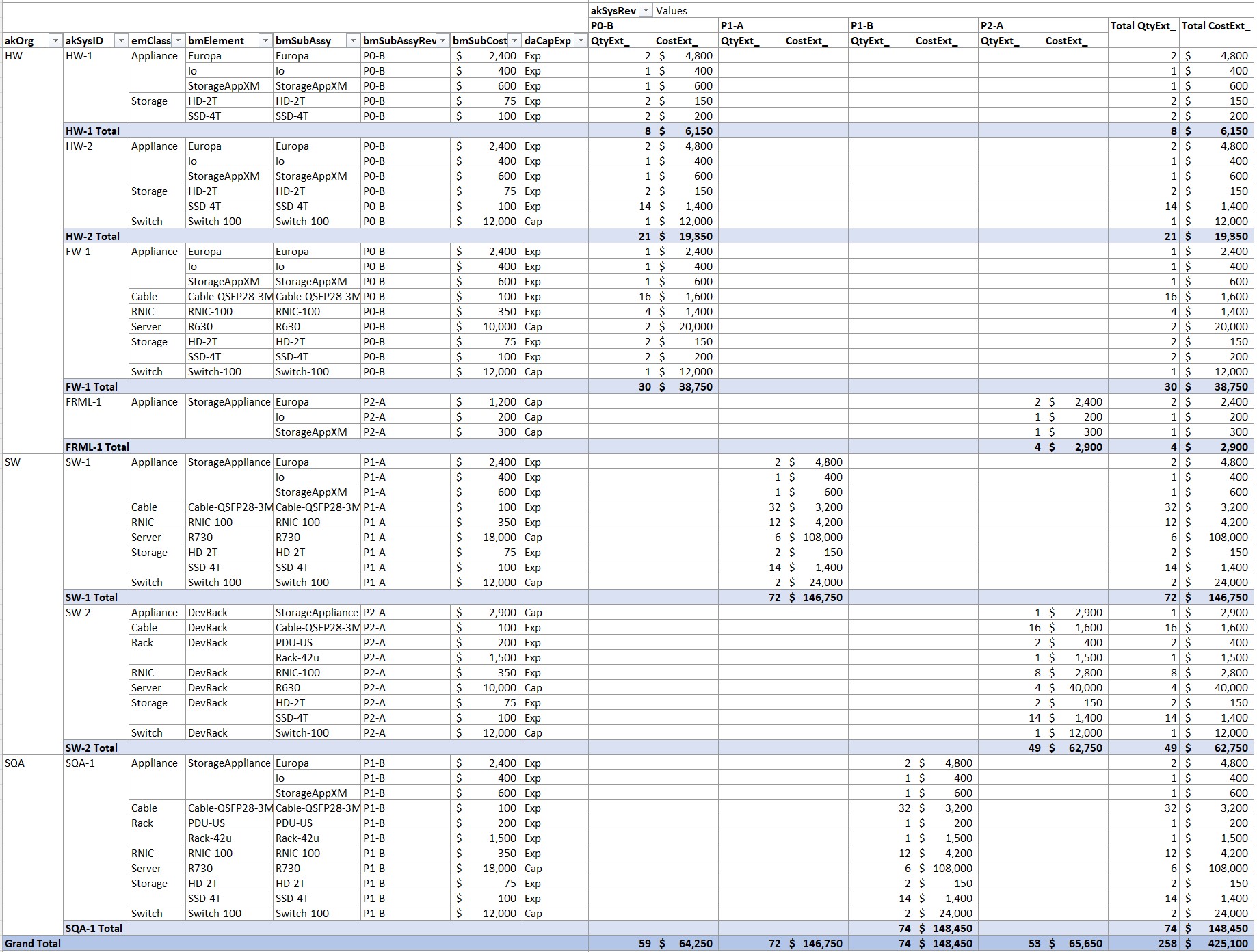
The sequence for component purchase has its own lifecycle and is described below. Purchase is often done on your behalf by the Contract Manufacturer (CM) constructing the prototype boards. Scarce or special material may be acquired by your company and consigned for use by the CM. These items may have long lead time, which must be included in the Program schedule. Scarce items may include new silicon ASICs, crystals, connectors, new cables, Zener diodes, and optics, and could have lead-time to 4-6 months. Jellybean items (resistors, capacitors, diodes, common silicon) have shorter lead-times, perhaps 3 weeks. You can plan purchase sequences as SF reverse sequences in MS Project or import the MS Project schedule into Excel and handle backward-planning calculations for lead time and approval cycles in Excel to keep the MS Project plan simpler. From Excel then you can produce automatic pivot reports on when to purchase materials with appropriate approval cycles, lead times, and quantities required, that support the SMT plan. Example reports are shown below.
Purchased Element Lifecycle: A Program usually has a set of elements and assemblies to be designed, built, and tested by the organization. But it also will use a set of purchased elements that can be several orders of magnitude more numerous, that must be acquired and qualified within Integration Cycle steps and deployed for allocated use among stakeholder organizations. These elements include power supplies, cables of many standards and lengths; numerous plug-in PCIe cards; Memory, dongles, and adapters; servers, switches, rack components; et al. This might also include IP from suppliers, Open Source, or Alliances.
Material acquisition for each of these built and purchased elements has a lifecycle all its own: identification/specification, supplier identification, purchase request to Supply Chain; RFQ (Request for Quote), Supplier quote, PO (Purchase Order), internal approval; supplier/distributor fab and lead time; shipment and receiving, staging, and warehousing; approval and payment; deployment per allocation, and tracking of material location.
Purchase Orders often need PO approval by Finance in a quarter preceding actual availability of material due to lead-time, which may require some negotiation with Finance who may not have considered lead-time. Payment for material and tooling committed to an order may be due when the PO is issued for mechanical parts or may be due on delivery from a CM if material can be re-directed if unused. Finance needs to be made aware of both planned PO dates and planned payment due dates.
Finally, keep in mind that material management almost never executes according to your simple plan, so time for mitigations due to partial/late/short/defective material is inevitable.
Mechanical parts include board stiffeners, brackets, front panels, and heatsinks. These are designed in your Program and purchased to your specified design using the Purchased Element Lifecycle. Mechanical material is usually charged when ordered since once committed to a design it’s not re-usable by the supplier.
Tooling may be required by the supplier prior to the ME part fab. Both tooling time and cost should be included in the Program schedule and logistics plan. Soft tooling may be available for early protos, but for later proto cycles leading to production, hard tooling will be needed, requiring much more time and cost. For bent metal this is not too huge but for molded plastic or metal machining or injection molding both time and cost are substantial.
Net, the Program schedule must include design, tooling, and fab time and cost for metal parts for each board element and assembly, for each build and Integration Cycle. Board-level ME parts are usually bent or machined metal and those can be planned in Excel as mentioned for component parts, planning lead times that include internal approvals. From Excel, you can produce automatic reports on when to start tooling and build to support the SMT plan.
The sequence for board construction includes acquisition of fab material for all board layers, specified by physical and electrical design of the board. These are acquired by the board fab supplier and take typically 2-3 weeks, plus possible shipment time, and cost several thousand dollars. This time and cost should be included in the Program plan. I usually buy board material “at risk” after the first fab of a board without waiting for final confirmation that design changes have not changed material construction. Risk of change is low, I can save adding that 2-3 weeks to the schedule, and if I’m wrong the cost is low.
Board construction then goes to fabrication of the board itself. Typically, board fab is done locally for early build cycles to use short fab cycles at low volume, and to eliminate shipment time. As the Manufacturing track moves proto to production facilities about P2 phase (see the Tracks image above), the fabs should be created at the intended production fab supplier. Later, alternate-source fab suppliers as well will have to be qualified by testing. The resulting board fabs are then shipped to the board construction manufacturer, typically a Contract Manufacturer (CM). The build cycle plan should incorporate fab time 1 week for early short cycle fabs, and 2-3 weeks from production fab suppliers plus 1 week shipment time to the CM if either is offshore.
SMT The CM solders the purchased components to the fab boards (SMT step – SMT is “Surface Mount Technology”), inspects and tests them, and assembles mechanical parts onto them. There is setup time for their automated equipment, and time for basic inspection and test. Scheduling about 2 weeks for construction gives you some minimum latitude. Later prototype builds at a production facility should add about 2 more weeks for board test to first article, and at least a week for shipment to you. Include these in the Program schedule for each element, each Prototype Cycle. In early builds I usually plan a small initial run to check for problems, followed quickly by a run for the bulk of units allocated. Buy all material for initial and bulk build up front. This build split has to be incorporated into material and build plans. The production facility incorporates test automation, higher volume, and production material contracts so unit cost is lower than for earlier prototypes although cycle time is longer.
Integration: Program-level Integrations Points (specifically, SMT Start) and Integration Cycles, with tributary element integrations, drive logistics and Program schedule. Integration Cycles and contained Integrations Points focus all organizations on meeting integration functionality and dates. PM focus on meeting Integration Points across all organizations with adaptation if needed, will greatly help the Program to stay on plan, so this is a key activity of Program Management.
To start an integration task, all involved Elements must be on-hand, built or purchased (power supplies, cables, plug-in boards off-the-shelf or custom) in the current Build task sequences or in a prior one. Software functionality must also be ready. Integration is usually done at your site right up to the last phases in the Program. All Elements must be available for integration, and for participation in the Qual test cycle of the current Integration Cycle.
Off-the-shelf items (power supplies, plug-in boards, cables) are purchased via the Purchased Element Lifecycle, scheduled backwards; I usually handle this scheduling in Excel as described above. More complex items may need configuration before they are used in an assembly – installation of firmware, security keys, etc., needing special facilities and time at the integration facility that should be planned into schedule.
Software Elements agreed for Integration Points should be available at the planned Integration Point, integrated, SQAed, and distributable internally. Late in the Program they should be distributable to Alpha, Beta and Early Adopter customers as well.
Integration Cycle Progression: The Program evolves as it progresses through Integration Cycles. Builds and tests are targeted sequentially through low-level bringup, then assembly bringup with broader distribution, then qual and certification, and finally customer exposure. As it evolves, the nature of Integration Cycles progresses in terms of configurations needed, build volume, and unit cost. Remember that functionality and tests defining the Integration Cycles are defined in the table specifying function and test for each Cycle. These factors enormously affect the logistics and budget for the entire Program, and this is the bulk of what must be quantified for these programs.
Early builds are small, to be used for hardware, firmware, and driver development for board bringup, configuration, and functional operation. Once initial stages of those result in operational hardware, then margin and corner checkout and problem mitigation begin, together with early driver bringup. For mechanical parts, dimensional and tolerance analysis ensures stable yield, cost and reliability. These early builds are limited to a handful of units, for bringup and debug of low-level hardware and firmware operation. Configurations are limited to simple chassis configurations supporting bringup and test of individual boards. Each unit is relatively expensive, perhaps 4x expected production cost due to manual assembly and test by high-skilled people, and low-volume component purchases that may include early generations of critical parts.
Net: lowest unit volume, simple configurations, highest unit cost.
Middle Builds are larger, for broader distribution of more complex configurations. Hardware continues corner quals and prepares for formal qual testing (environmental, ESD, reliability) driven by diagnostics. Test development accelerates, leading to manufacturing test automation for individual units and built assemblies. As drivers and system management mature more units can be distributed to broader areas of platform development, new function, and development and integration with middleware, application environments and configurations. Most of these units are distributed as limited-configuration assemblies since most development doesn’t require full configurations. Some are integrated by your IT or Lab into limited-configuration systems. A few large systems are built, for work on performance and configuration limits, for SQA and for formal Qual (corners, environmental). These assemblies are probably built at a CM production facility, implementing test automation, production assembly lines, and volume component purchases. System integrations are handled by IT or Lab.
Build Cycles at this point are not limited to the target product under development; they must increasingly include off-the-shelf production equipment and are built as systems that utilize the target product: racks, backplanes, clients, servers, switches, cloud services: all equipment and services relevant to use your product. These systems are increasingly configured by IT as they are provided to development that may be distributed geographically. Logistics planning and execution at this point expands to handle boards, assemblies, and full systems.
Note that your product may be the targeted system element (processor, network, storage etc.) and that although built and configured systems may never be a product of the Program, nevertheless the Program needs to do material, logistics and financial planning to build full systems for internal use and distribution.
Net: high unit volume, mix of simple configurations and large configurations, mid-range unit cost.
Late Builds are more fully configured versions. These are used for SQA leading to production, formal Qual activities (safety and emissions compliance, thermal/environmental/ESD validation, security and financial certification et al.), and exposure to real customer workloads including development of higher-level system function and application software. These systems are built in some volume for the distributed base of internal and external users and early adopters. Builds of the product are closer to intended production cost due to test automation, production Supply Chain contracts, and production facilities at the CM.
Net: highest unit volume, largest average configurations, lowest unit cost.
Note that although prototype cost of built units starts as expensive and declines over the course of the Program, cost of all off-the-shelf equipment either contained in the product (plug-in boards, power supplies, cables) or used with it (servers, switches, racks) remains constant from early prototypes into production. Higher-cost items may be capitalized.
Plan Updates: It’s important to update the Program plan schedule and logistics to reflect build completions, cost updates, and in fact any aspect that changes the schedule critical path, build plan, or the budget rollup so that critical items that might be considered KPIs (Key Performance Indicators) will be up to date. Update fab times etc. to reflect reality, and keep Integration Points and Integration Cycle dates accurate so that future dates will reflect that reality. This supports day-to-day program decisions, Program changes, problem mitigation, and status reporting in management meetings, quarter- and annual budget reviews. This will also be useful if the plan is archived on release, to reference when making time, cost, or other estimations for future projects.
Backward Compatibility: As a Program develops, changes to design may be necessary. If possible, implement these changes with backward compatibility. If not thought out, a small incompatible change to a board could require replacement of a whole chassis in equipment previously distributed. You don’t want to support multiple incompatible prototype versions. But replacement requires cost and time to build, and then skilled labor to update and checkout into installed prototypes. A small change not well thought out for compatibility can magnify into a big logistical nightmare and time sink. Incompatible changes can be implemented if absolutely required, but cost, time and effort of change should drive real consideration of alternatives.
Similarly, hardware should be fully capable and tested when shipped even if software to use all its capabilities is not complete. It’s usually impractical to update low-level hardware in the field, instead requiring wholesale replacement of assemblies and thus requiring production cost, time, skilled labor, validation tools etc. Another logistics storm is easily created. Firmware can be updated and that may cover functional or configuration deliveries if necessary hardware itself is present. Again cost, time, and effort of field replacement is an important consideration.
It’s often the PM who must spot these in advance and prevent poor decisions.
DevOps: Develop a solid plan with DevOps for development on private branches, with integration sequences onto an integrated program branch. Program Increment planning can be used to map to your Program’s Integration Cycles to handle function-schedule dependencies, integration points, and Schedule.
Coordinate multiple Development Frameworks: Phased, Agile/Scrum, Ops/Supply Chain, DevOps, and partner methodologies may be simultaneously in action throughout a Program. Each organization can use their local framework to plan and to drive required function toward Integration Points where they converge. Note that Plan update is continuous activity, in parallel with execution of the plan.
Acceptance Sampling: Statistical Process Control (SPC) is used for production of some “commodity” purchased items statistically tested because of volume, price point, and test time. If your Program prototypes find an item that fails in several instances and can be fixed by replacement, that could indicate weak manufacturing, latent failure, or low margin. You don’t want to go to production with any of those, and this should be prevented within your Program development.
AQL (Acceptance Quality Limit) testing by the manufacturer could be limited by inadequate sampling or inadequate testing. Your Supply Chain should be on top of this for production items, but if your Program is using a newly available item, your Program may be the first to run into a problem. Amazing how many problems you’ll be “the first” to encounter. Here’s the PM view.
I advise care when sourcing items for extremes in bandwidth, voltage, current etc. If you see part variation in your prototypes, test your own sample population of the suspected part. Your CM may be able to do this and report to you. Extend functional test, add margin test, add de-construction and inspection. You may find wires connected by solder bridge, insulation stripped beyond spec, inadequate strain relief, margin out-of-spec.
Depending on what you find, you may want to specify or negotiate details of the suppliers’ AQL procedure. There’s a book referenced on my website, Zero Acceptance Number Sampling Plans (Fifth Edition). You can insist on parameters that result in zero defects, or a defect level you can tolerate. SPC for Zero Acceptance Number Sampling should include specified testing of suitable samples, for function, margin, and inspection of construction.
On receipt of a lot failing your acceptance criteria, reject the whole lot. You’re probably not the first to see the failure, it’s possible that you’re receiving material rejected from stricter lot testing for other customers. You may end up eating latent failures in your development or in the field. It may be possible to default to 100% test on AQL failure but if construction analysis is destructive then only sample testing with failed-lot rejection is going to prevent latent failures. For supplier AQL in production, your Supply Chain or CM should periodically audit supplier AQL records and processes.
Holidays Be aware that offshore companies observe national holidays different from US holidays. I schedule Christmas break for US suppliers, and Lunar New Year and Golden Week for Asian. I typically don’t schedule individual day holidays into the schedule since Program task execution is not usually predictable and stable to the individual day, and one can always find a workaround to limit effect of any single-day holiday as it occurs. Some suppliers work a 6-day week. In MS Project you can create regional calendars and assign them to a regional resource, then assign the appropriate regional resource to scheduled tasks.
Use the quantified plan in execution. Continuously update quantification; track progress and mitigate discrepancies and divergences immediately. Your program should never have a failure or bottleneck due to lack of planning of these elements and sequences, and you should never let the plan fall out-of-date. It’s way more effective to keep a plan up to date than it is for the organization to respond to the result of a planning failure.
Drive Materials Logistics
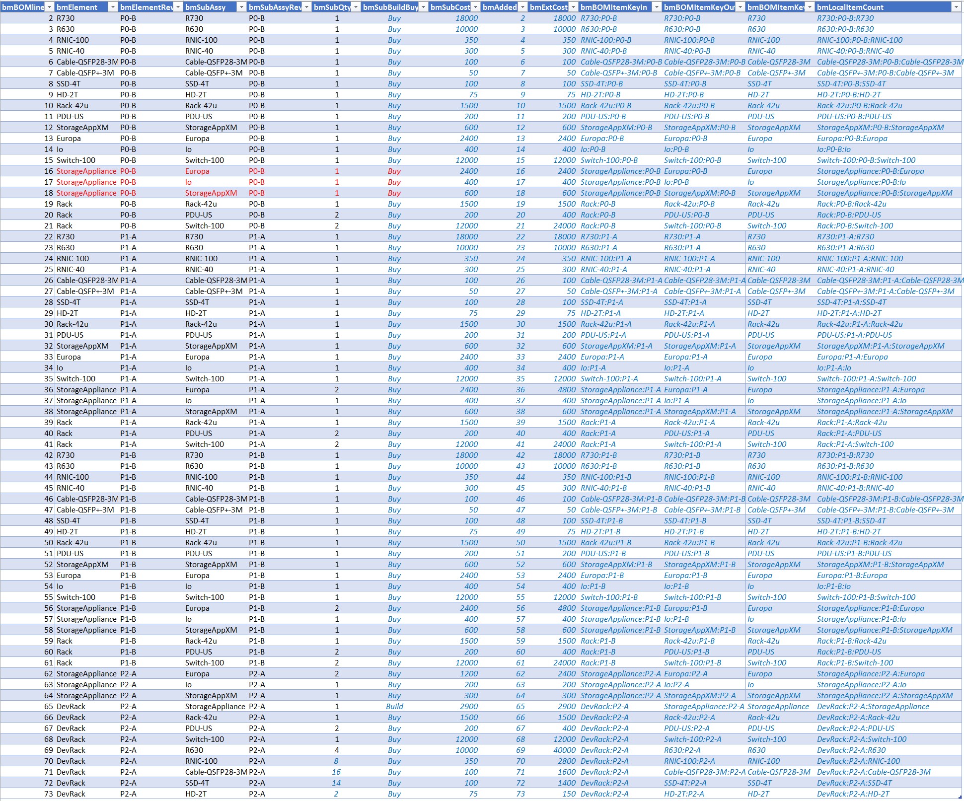
Quantification of Logistics involves several sub-plans, represented by data tables. The Allocation plan quantifies who is going to use items, what kind, what configuration, quantity, for what, and when (usually by Phase/Integration Cycle) and resulting in build and expenditure. The Program BOM identifies product planning-BOM structure defining components, elements and assemblies that can be allocated, then built or purchased. This is not the formal MRP BOM (Manufacturing Resource Planning system – Oracle, SAP et al. Bill of Materials), but is abbreviated quantification of key materials needing management. It also includes placeholders aggregating jellybean components to roll up planned element cost.
The Allocation Table is JOINed with the Program BOM to explode systems to elements, assemblies, and enclosures; assemblies to boards and metal; and boards to components; and then JOINed with dates imported from the program task Schedule plan incorporating function-schedule dependencies, sequence, and planned duration. The Schedule includes tasks for build, integration, and distribution to use. Finally, that result is JOINed with element data including cost, supplier and other product specifications affecting logistics. These JOINed tables together yield quantification of financial outcomes. Continuous planning keeps these execution plan dimensions, and derived financial plan, up to date, reviewed, and executed.
JOINs are database operations that combine the data tables, to figure out the many combinations of parts, builds, uses, suppliers, dates and the many more data points. The result of the JOINs is a large data table that can be mined to produce real operational plans for Supply Chain, Operations, Engineering, IT and others. The example tools linked here show how that’s done, using common desktop tools and extensible to enterprise tools.
The example tools linked in this blog post (free) can adequately represent such a plan structure to any needed level of detail or abstraction, coarse or detailed. Importantly, they support fast planning to support Agile Mindset by informing short-term decisions and implementing their logistical execution. Tool automation minimizes work penalty for planning, automatically maintaining referential integrity among multi-dimensional plan aspects. The tools are fully functional, representing all aspects of quantification discussed here; and of course, are optional or can be referenced to illustrate examples of structure. Additional Tables may provide additional functionality beyond quantification shown in this post. You can build your own tools too – the point here is that good tools supporting planning and execution can make agile behavior possible in complex projects, avoiding quantification errors in the process.
The following illustrations of quantification are from the example linked tools for clarity, but your tools may be implemented differently. There’s a discussion of several possible architectures for quantification tools at Quantitative Management.
Allocation: Represents use, configuration, Integration Cycle, and quantity. Includes key-fields for local cost aggregation and JOINs to related tables including Program BOM and element data reference.
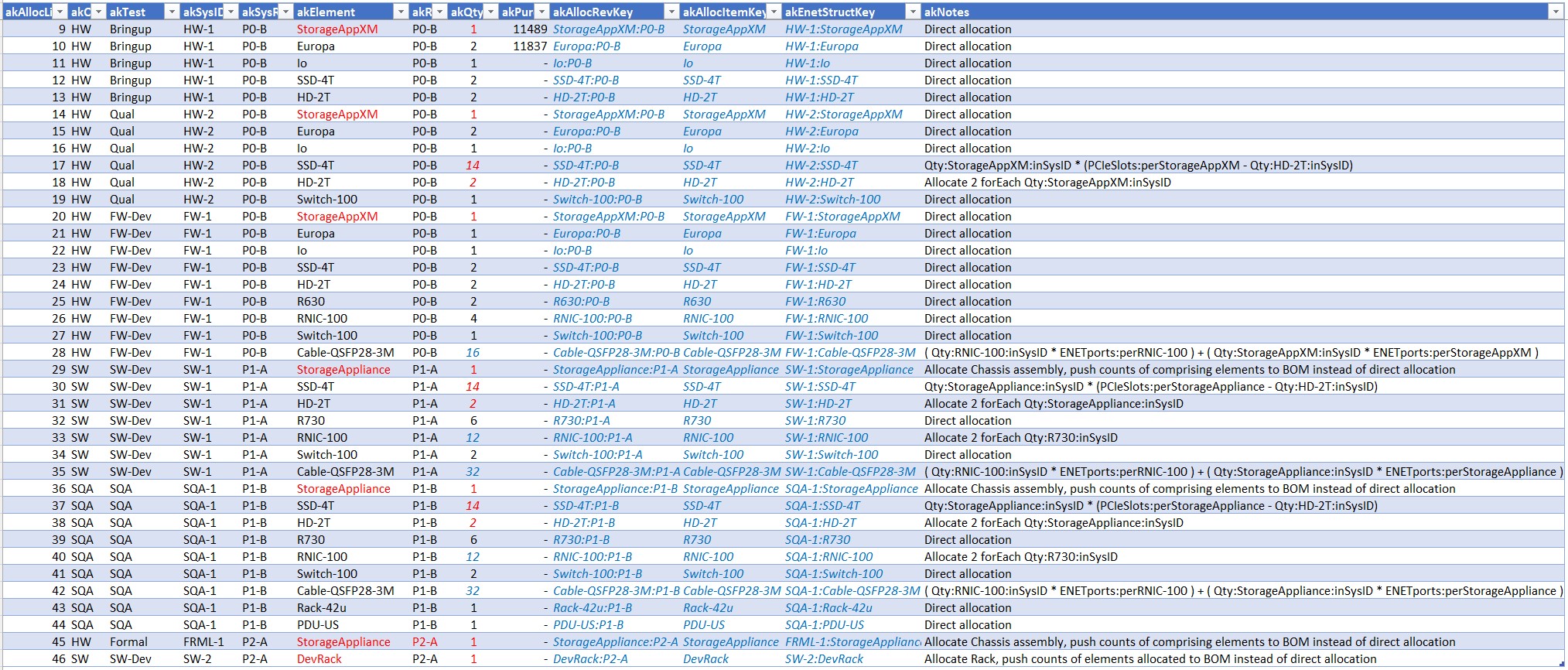
Program BOM: Represents a Product Tree structure including components, built items, assemblies, and systems, for each Integration Cycle/Phase. Includes key-fields for JOIN.
MS Project Import: Raw data import from MS Project for task data. In the MS Project file, field “TaskMilestone” has been added and populated to provide a key-field for JOINs to related tables.
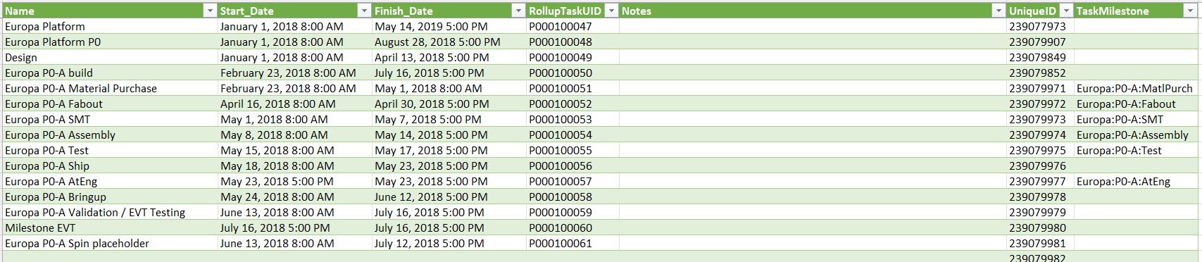
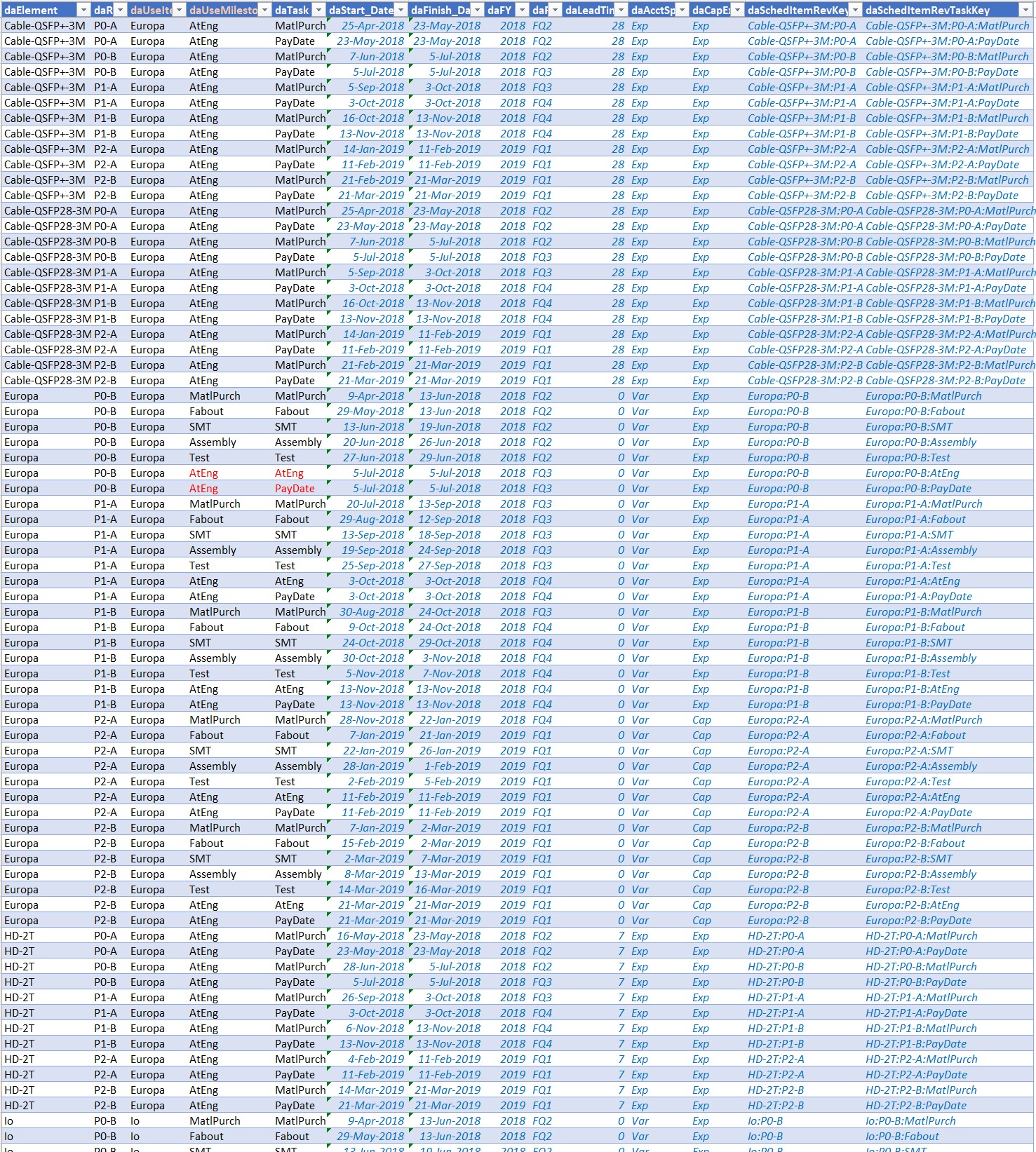
Dates: Normalized table associates dates from MS Project import table with Program BOM items. This table implements date aliasing to support purchased items not represented in MS Project that can be synced to builds. This simplifies scheduling of those items that do not need task sequencing. Key fields for JOIN are included in the table.
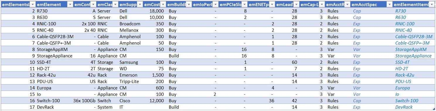
Element Data: Raw data for each component, element, assembly or system item planned. Configuration detail, cost, supplier, distributor, slots, ports, cap/expense rules, lead-time etc. – any item data to be included in reports of affect rollup in other tables. Includes key-field for JOIN.
VLSI Die Logistics: Tables can manage planned and actual die allocation among wafer lots. A table for fabout and build planning would include dates and quantities for tapeout, substrate fab, metal fab, test probe and packaging substrate including planning for any deferral of metalization, probe test, and packaging. Probe test count could be recorded to manage probe limit. A table for wafer planning would organize die allocation for each lot by wafer, to allocate die usage among process-corners. This is particularly useful for planning corner lots exposing the chip design to multiple mixed-domain process variations (e.g. SFFT slow-fast-typical), and provisioning operational use of yielded die. Fields for test status by die can manage process-corner yield, and selection for yielded-die allocation to packaging and product test.
Data specifics for these chips, managed as part of an overall Program and used within program product assemblies, can be added as components into tblBOM above. Use of specific process variations can be accomplished by appropriate chip naming in the wafer management table above or by other linking key construction. Chip dates can be added into the overall GANTT, or linked into tblDates. tblElements can include chip entries for cost, supplier, power, etc. Purchase order data for chips can be included into tblPurchReq, with Purchase Order number added into tblAlloc.
This methodology of adding tables to accommodate specifics managing creation of use of VLSI technology within a Program, generalizes to make it possible to add other technologies requiring specific management into the Program Plan.
Drive Program Financials
Program financials require active, constant work on a Program budget plan at Program commit, at Annual budget plan, at quarterly actuals and outlook reviews, for supply chain execution, and for expense and plan change mitigations. When the plan is developed initially, it will need to be iterated to best meet objectives for Program delivery dates, and for ROI or NPV. This will require fat removal, better planning, and incremental tradeoffs to maintain product objectives for availability, cost, and quality. This is the connection of the Program to the business of the organization. You’ll find we all actually work for Product Management and Finance operationally, if not literally.
Both software programs and hardware programs deal with financials to cover staffing, both permanent and temporary, over the course of a project. Staffing of an organization usually remains nearly constant leading to a pretty flat spend rate, and its financing may even be planned outside of assignment to specific program efforts. Program characteristics, and assignment of staff among Programs, usually affect funding of organization staffing only minimally since organizations typically plan for work that nearly fits within current staffing. The problem is usually to balance staffing assignment among Programs within a common headcount.
However, Programs dealing with hardware introduce important levels of expenditure focused on physical hardware builds subject to dates, lead-time and partners. Usually there are a few elements with very long lead times or limited availability, implying planning far enough in the future so that those elements will be available when needed. Hardware Prototype Cycles incur incremental material and labor cost that spikes at times when prototype integrations occur. These cost amounts and timing need to be predicted to corporate Finance well in advance (Commit, Annual, and Quarter visibility) and are therefore the subject of the budgets and reviews listed.
Hardware to be supplied for Software development is usually the bulk of material expense (80% of material cost not uncommon) but is usually covered in Hardware budgets due to its intimacy with the hardware build/acquisition processes. This causes a quantified mutual dependency between development efforts for hardware and software.
Once set at annual or quarter intervals, budget is rarely adjusted; the Program must almost always adjust its plan instead!
Expense and Capital Accounting Program material may be accounted for as expense or as capital depending on its cost and expected lifetime. Early prototype hardware would be accounted for as expense. Later prototype hardware systems for ongoing and post-FCS SQA or performance testing might be capitalized. High cost purchased items like included servers or switches are capitalized unless they will be exposed to a destructive environment. Both hardware and software programs need capital equipment, licenses for libraries, tools, and runtime software. We must also account for partner services. These are accounted for as expense items if small or capitalized if large. Cap/Expense status for each item is represented in an appropriate source data Table, to be used or aggregated in resulting Reports.
It’s usually the system Program Manager who must identify, plan, and execute these assignments – you’re doing the budget after all, usually long before anybody has thought about this.
Full Program Budget Prediction and management of these function-schedule dependencies, lead times, incremental costs, prediction, acquisition, and accounting differentiate hardware Program Management from software-only Program Management. Management of these costs, and of Program schedule optimization are drivers toward Phased program methodology since its Phases are easily mapped as Integration Cycles. Specific methods and tools that handle these are linked below in the section on Core Program Quantitative Structure for System Programs.
Program Management produces the full Program cross-org Budget at commit, and subsequent quarterly reporting of Planned and Actual expenditures, Expense and Capital. Unit allocation, combined with product structure and development schedule, drive the Program financial plan. The Program Manager is responsible for planning and reporting Program costs planned and executed for Program work by all stakeholder organizations, with contributions provided by those stakeholders. The PM drives cross-org Program Annual budget, and Program Quarter outlook and Finance actuals with input from stakeholders and of course drives mitigation of financial conundrums, and changes to plan.
Reports From Program Plan Inform Operational Actions: Tables enumerated previously, (Allocation, ProgramBOM, Dates and Element Data) are read from Excel by the database environment, where they are combined by JOIN operations. In the (free!) tool linked below, the database could be PowerQuery, MS Access or SQL Server; or of course you can collect the data and combine it within your own design perhaps using the linked tool as an example. A QUERY from Excel containing SQL or M initiates the JOIN and returns the result, which is capable of driving many reports useful to organizations implementing the program Plan. Typically, Excel uses the QUERY as a data source for Pivot Tables, Structured Tables, or Pivot Charts.
The result of a single QUERY can drive multiple such reports. Typically, there are numerous reports for Development, for Supply Chain and Operations, for Finance, and for Program Management. Here are some examples of reports, customized to the organizations that use them. These are examples from the linked Tool.
A report summarizing equipment allocated to Development, by organization with equipment detail, its use (indicated by named SysID), its targeted build in an Integration Cycle, then its quantity, cost, and capital/expense status.
A report for Operations listing dates to plan and execute board builds within each Prototype Cycle; and assembly, integration, and test. The report results in a table of many dates, so Excel conditional formatting is used to highlight and alert for actions upcoming shortly, and for actions that should have been recently completed. Dates for operations completed further back in time are shown muted so that upcoming operations will be shown more prominently.
A report for Finance showing all expenditures summarized by item, and by Fiscal Date. Dates in other reports for Operational tasks are shown using calendar dates but for Financial reports, dates are translated to Fiscal dates within the Excel PM tool. This translation often falls to Program Management. Typically Finance uses many reports for planning and actuals, for expense and capital items, for cashflow timing, and many more.
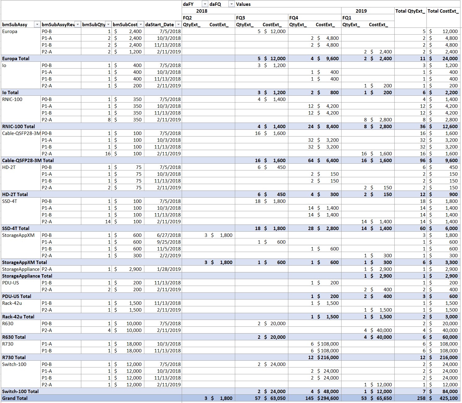
A report planning Purchase Orders, and tracking progress of items purchased. Purchase Orders are planned to start in time for item deliveries for builds – dates for built items are shown in the Operations report above. And it doesn’t make sense to start a build unless necessary items have been delivered. Once delivered, status tracking of physical storage and distribution of items helps prevent “lost” items from impeding progress implementing the program plan.
Key Program Artifacts
The PM must develop key Program artifacts through the course of the program, in writing, and must archive and index them. Many of these require contribution from stakeholders throughout the Program. The plans described above are a substantial part of this. Usually, the organization requires archiving, which helps with Program Retrospective, planning of subsequent Programs, and may be required for ISO or other compliances which might be required by customers. This material is always useful for communication in many scenarios.
These artifacts should be those that are useful to real work, not documents for the sake of bureaucracy. The PM should be actively anti-bureaucracy, against effort that wastes time and effort. Documentation may be de-prioritized in some frameworks, but there is some that is actually useful to planning and execution of work so do create them and use them. Some may also be required among organizations within the host organization.
- Plans, diagrams, presentations, tools, special analyses, etc.
- Proposals, Program Commits, Quarterly Program Reviews, FCS Commits, Agenda and Minutes of organizational meetings, many of the core team meetings.
- PO Requests.
- Partner and Supplier Statements of Work.
- Quality, Compliance and Certification preparation and reports: Security, emission, safety, ISO et al.
- Design documentation for later Support and Enhancement. It is easily possible to create product elements that take years of experience to be able to support due to Spaghetti code or just complex distributed designs. Often support is done in a separate organization that may be geographically distant. Documentation can help organizational operation and product integrity and regression.
A practice that worked well was to develop skeleton descriptions of logical and physical architecture and APIs, and then to finalize them incorporating implementation changes at Program Release while thinking is still fresh. If well done, this can provide great leverage to Support ability to fix defects, as well as to Development to decrease experience required to create enhancements without introducing defects or regressions.
PM Information Breadth and Depth on Program, Product, and Organization
As described above, Program Management involves
- Creating, Integrating, Executing and Managing these plans.
- Envisioning and modeling aspects to the product detail and structure needed to determine program schedule with dependencies.
- Determining schedule for acquisition and spending, based on equipment need and usage.
- Determining material acquisition, build and integration.
- All these 6 months to a year ahead of actual task execution to be ready with material needed. Continuously updated to reflect the future as it comes to be known.
- Steering all those aspects through the organizations to execute the tasks.
- Adapting to plan changes, material and build issues, and bugs.
These make the Program Manager look so deeply into the Program and Product as to acquire and maintain un-paralleled wealth of information about the Program, the product and about the operation of the organization.
Program Meeting Structure and Agenda
Program Management communication needs effective meetings. We don’t need meetings for the sake of meetings, and meeting participation is neither reward nor punishment. Instead, meetings can be hierarchically related to Program elements, major tasks, and Management Structure so that people attending each have a role in each meeting, and don’t need to be bored, or work on email, or go surfing.
Small meetings are for discussion and decisions. Large meetings are for information broadcast, awareness, and questions. Project Managers or Dev Leads are usually capable of leading element technical meetings on design planning and execution including technical cross-functional stakeholders, with Program Management participation for logistics, work prioritization, and guidance. PM usually leads Integration and Management meetings requiring cross-functional interaction, logistics, finance, and Management. PM also usually knows each element status well enough to handle element meetings when needed.
Weekly
- Element-level cross-functional small-focus meetings.
- System Integration Cycle and Proto Cycle builds cross-functional meeting.
- Software integration, DevOps, Triage meeting (These could instead be daily Scrum Stand-ups as needed by Framework).
- Senior management meeting. Business, Status, Issues, Outlook.
Of course, maintain an ongoing agenda chain through each of these meeting sequences.
Monthly or Quarterly:
- Cross-organization meetings for information dissemination, questions.
Quarterly
- Review and Demo to senior management.
Further Reading: Core Program Quantitative Structure for System Programs
Advice for Program Managers: The Blog Series
1-Program Management Opportunity
Introduces a vision and framework for development of Program Managers and PMO, for Program Management specialization to its environment, and for improved effectiveness and integration of PM with organization
operational management.
2-Program Management Career Path
Describes career path thinking for Program Managers including sourcing, progression, advancement, and connection with organizational management.
3-Program Management Career Skills
Career path thinking for Program Managers including skills and behaviors that develop Program Manager capabilities and leadership and pave the way toward advancement.
4-Program Management Specialization: System Programs Phased Methodology
PM Best Practices and Core Program Structure for Hybrid integrated system programs using Phased HW – Agile SW, mixed-technologies. Full-Program agility via automated plan tools with continuous plan update.
The Series also solicits contributions to this Blog site, to extend coverage of PM Best Practices and Core Program Structure to a broadening set of Specializations.
5-PMO Role
PMO behavior to achieve Program Management effectiveness specialized to its environment managing PM practices in the organization, including PM development and advancement and connection with organizational management.
6-Quantified Agile for Hardware
Program Quantification applied to Phased and Agile methodologies to deal with organizational quantitative requirements.
More Articles by this Author
Guiding Principles for Program Management Action, Program Quantification, and Leverage Through Tooling.
Organizing Program Communication
Program Management depends on effective communication. Design Program communication paths for everyone throughout the Program.
Database Platforms for Program Management Logistics
Logistics Tool extended, using SQL Server and MS Access with MS Excel and PowerQuery.
PowerQuery Tool
Logistics Tool using MS Excel Power Query.
Quantitative Management
Tool methodology for agility with continuous plan update: Program BOM, Tie to Dates, Builds, Element data.
Complex Programs: Structure
Structure Program with Parallel Phasing. Describes coordination of EE/ME, FW, Test, Supply/CM, Driver/Kernel, Transport, Management. Scheduling, Integration points, scaffolding, and starting work. Hybrid Program Cross-Domain Coordination of dev frameworks, including Phased and Agile/Scrum where appropriate, via integration points and scaffolding. Software Integration Sequence and Dependency Planning.
Managing Complex Projects
Problem Statement. PM responsibility for Program Management drive throughout an organization, also includes schedule, budget, integration, critical path, logistics.
Program Roadmap
Planning work structure for a Program, and using the plan effectively.
Lifestyle AI
AI effects on current and future lifestyles. Personal strategies for proactive and defensive use of AI.
Iterative Thinking
Using Iterative Thinking to solve big problems and complex logistics.
Link To Free Tools To Manage Schedule, Logistics, And Finance
Author’s softtoyssoftware.com website with articles on Program Management and Program quantification tooling using Excel, MS Project, and MS Visio with SQL databases PowerQuery, SQL Server, and MS Access. Articles describe how you can use tools available from the website, or develop these capabilities yourself using commonly available tools.
Tools available from this website are free. They can handle small to large programs, limited only by your imagination. Using the included Program Template to envision, organize, plan, and run a large program puts me in mind of unleashing a Roman Legion to a sure outcome. Veni, Vidi, Vici! – Julius Caesar.
- https://www.softtoyssoftware.com/dbnet/programmingprojects/powerquerytool.htm
- Details on design of Structured Tables, JOINs, Reports/Pivots in Tools.
- Schedule, Visualization, Reporting.
- Hybrid program agility with continuous plan update.
- Microsoft 365 Desktop – based.
Credits
Image(s) used under license from Shutterstock.com. Attribution: Rudenkois / Shutterstock.com
My website: www.softtoyssoftware.com
Copyright © 2021 Richard M. Bixler
All rights reserved

This is for سئو/ بهینه سازی فنی
Following and enforcing Richard Bixler’s reply comment, this blog is for all Project, Program, Portfolio, and Product Managers (with or without an Agile mindset). Please create your account and let us know you want to post a blog related to Agile and Scaled-Value Project Management (ASVPM.org), and we will give you “edit” access to our system.
hey there and thank you for your info – I’ve certainly picked up
anything new from right here. I did however expertise some technical points using this website, as I experienced to reload the web site a lot of times previous to
I could get it to load correctly. I had been wondering if your
web hosting is OK? Not that I’m complaining, but slow loading
instances times will sometimes affect your placement in google and could damage your high quality score if advertising and marketing with Adwords.
Anyway I’m adding this RSS to my e-mail and can look out for a lot
more of your respective exciting content. Make
sure you update this again very soon.
Hello – the web hosting for svprojectmanagement.com is shared among all who post here and I haven’t seen any problems reported. I don’t have control over the host parameters anyway…
The thing I see that is somewhat unusual about my post that you reference is that it has several images. Those load fine on all the configs I’ve tested with Windows and Android using Chrome, Edge, Firefox and DuckDuckGo. I’ve had limited exposure on Mac and iPhone. Could you say what client and platform you are using when accessing this post?
I notice your ID on this site is in script: I’ve only tested within the US; if you’re outside of the US is there any possibility that image transit to your client causing the problem? How does my post compare to other image-heavy pages?